
For the last three weeks we have been working with powercopies (smart cells), understanding the potential, behavior, advantage, and logic of such a digital element in the design process. In "Knowledge Patterns", which is the assignment for this week, we are scripting the instantiation process of the User Defined Feature (UDF) or "special powercopies". This process allows us to achieve the required complexity in a digital model (through increasing or reducing the use of powercopies on a surface). In addition, the automated - and parametrically driven - process also allows the possibility for adjusting and revising the work, unlike the previous attempts in using powercopies.
In this assignment, and after going through the "bigger picture" and goals of knowledge patterns, we first create the layout (framework) for the work that will follow. But, in knowledge patterns the process will be slightly different and a will include a level of procedural complexity. We start with a surface (using either filled or multisections [opened or closed]) and then elements (points and lines) that will help in defining its contour later on.
To achieve our goals in this project, we had to understand the logic and sequence of scripting the UDF. In general, the process start with a "design file" that basically includes the geometry (image 1); what follows is the "UDF", which is a "special powercopy"; and finally, the "catalog" where the UDFs will be placed for the design file to locate and recall when using the knowledge pattern.
To achieve our goals in this project, we had to understand the logic and sequence of scripting the UDF. In general, the process start with a "design file" that basically includes the geometry (image 1); what follows is the "UDF", which is a "special powercopy"; and finally, the "catalog" where the UDFs will be placed for the design file to locate and recall when using the knowledge pattern.

Image 1: shows the geometry (filled surface), which is the first step to define the work layout.

Image 2: Then we create three main parameters, which will control the number and position of the contour lines (framework) on that surface. The inputs of the parameters is, basically, two points (one on each curve) with a line that connects both.

Image 3: After the geometry has been created, we start the first UDF. This step requires additional and precise information (also case sensitive) to create the UDF, unlike previous work with powercopies.

Image 4: After the UDF is created a text file of all the information related to the geometry and its parameters is created. This text file is the information that is required as inputs for the catalog and script.

Image 4: The catalog as mentioned will locate the information related to the geometry from the UDF text file.

Image 5: Shows the window from the "knowledge advisor's" workbench, this window will include the CAT script that will create and control the contour lines on the surface in response to the change of inputs and parameters.
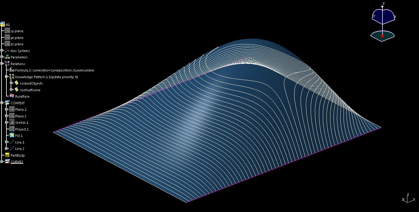
Image 6: Shows the scripted contour lines (framework).


Image 8: Shows how the contour lines in response to the change in geometry; in this case the hight of the passing point on the filled surface.
Comments
Post a Comment