
Knowledge Patterns: Surface Panelling


We have been working for the past five weeks with Powercopies, a replication tool in Digital Project. But, the last couple of weeks we have been introduced to UDFs (User Identified Features), a tool similar to the powercopy, but much more advanced in the process of replication. we started exploring some of its abilities and potential last week (http://dtbyemad.blogspot.com/2013/11/knowledge-patterns.html) and continued this week to explore its power to panel a surface, basically, the possibility to cover a surface with a large of the same unit while being generatively responsive to its context. In part two of Knowledge patterns we will cover the framework that we have developed last week with tiles (in this assignment; surfaces). 

 A short brief on UDFs, they are similar in nature to power copies (replication tool), but are used to cover large areas with large numbers of the same unit (geometrical set that consists of curve, surfaces, point, parameters, constraints, rules, etc.). 


Image 1: surface panelling consist of the same steps of creating the frame, which will be mentioned as we progress in this post. This image Shows the frame work from the previous post. 


Image 2: First, we select two of the curves from the contour lines and copy them. 


Image 3: the contour lines are pasted into a new part as special features. SFs are geometry that are not linked to the original file from which they were copied. 


Image 4: the process starts by creating parameters that define the units' which are: surface number (integer), surface position (integer), surface starting point (real), and surface ending point (real).


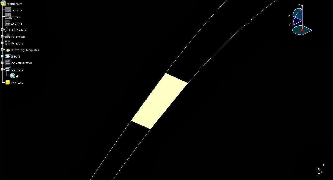
Image 5: after the points and the P-line that connects them are set (this is the information and geometry used fro this assignment) then a filled surface is created. 


Image 6: the surface and all the required information are used to create a UDF.


Image 7: the UDF is then listed in a catalog which helps organize, update, and recall all the required information for the replication process.


Image 8: at this stage, all our information is organized, categorized, and ready for replication. But before the replication process begins, we need to script the information - the interaction between both the framework and the UDF - so that we could obtain a higher level of control and desired results.


Image 9: shows the panels on the surface, the panels are also scripted to include RGB values that respond to their given information within the overall context. 


Image 10: shows how the UDFs respond to the change in curve number (starting from 10 curves going all the way to 73). What can also be noticed is that, the resolution changes, the higher the number of panels, the higher the resolution becomes. 


Image 11: show the surface with over 600 panels, and a framework that consists over 70 curves. This is one advantage of using UDFs, which is to cover large areas with large numbers of a single unit that could respond to any of its modifications parametrically.  


Comments

Popular posts from this blog

Folding: From The Physical To The Digital

This post is the third on the series of "folding" assignments. The earlier attempt of this project (http://dtbyemad.blogspot.com/2013/10/folding.html) did not show satisfying results. The form was controlled through a number of constraints and parameters that were not correctly assigned to the geometry, and the geometry itself in terms of its relationship - between one geometry and another - was not very well understood. So, in this post, the process of creating a "part" and a product was further investigated to achieve the required geometrical form and behavior.  Image 1: shows the intended form. The photos is from Paul Jackson's book "Folding Techniques For Designers From Sheet to Form".  Image 2: to be able to construct this form, first we will have to breakdown the geometry into individual  unit (a complete set of surfaces). Then this unit will be even broken down to individual surfaces, each surface will be separately placed

Algorithms: Design of Experiments

Design for experiments is an algorithmic based tool that is found in DP, which help the designer - us in this case - to evaluate and provide a set of possibilities for a designed object. This algorithmic approach and the operation of the tool relies on the set of data (input) provided that derive and control the possible results (outcomes); data in this case, are derived from the parameters that control the sketch. The value of this digital tool - and this computational approach - is to tackle design issues through a an infinite set of possibilities and outcomes, each of these results are evaluated based on measured properties, for example, in this assignment, the volume of the altered object is the source of evaluation.  Image 1: as any of the previous projects that have been presented, creating the sketch is the initial step. In this sketch the geometry (circle) is constrained and controlled through the construction geometry (horizontal and vertical lines), which are a

CORAL: D.O.E.s & Assemblies

Coral is a project that merges between both the Virtual Engagement and Materials Engagement classes. The goals of this project are: first, to translate the design from the digital environment into a physical object using knowledge and skills that we have developed in both classes during the past 14 weeks, and using state-of-the-art fabrication tools. Second, is to create a unit - part - that could be replicated and then put together  in an assembly - product. The assembly's dynamic nature was delivered through its parts that could be rearranged in various ways to produce different assembly configurations, and the ability to adapt to its context. The overall effect is similar to how a coral - organically - grows contextualizing its environment. As mentioned, the project will highlight some of the skills that were gained throughout the term required to complete this project, and are organized below as the project's development phases:  1. Digital Environment: 1.1. 2